Basic Settings
Basic Settings
Settings related to effect playback.
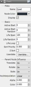
Meta
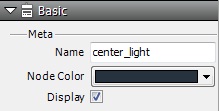
| Name | apply node name |
| Node Color | Apply colors to nodes in schematic |
| Display | Display/don’t display node materials |
Basics
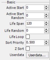
| Emitter Type | Set the type of material to be displayed. This can be set from Quad or Particle or Model or Stripe. |
| Active Start | This is the number of frames generated by particles. If you enter 10 as a value it will start playing from the 10th frame. |
| Active Start Random Range | Input a random range for number of frames to be generated by particles. If you input 10 for Active Start and 10 for Active Start Random Range it will be generate frames 5 through 15. |
| Life | Display time of particles |
| Life Random Range | Range over which the display time of particles runs out. Input 10 for Life and 10 for Life Random Range and the particles will randomly display between time 5 to 15. |
| Life Span Loop | If you check this option the life span time is infinite and display recurs over and over(from Version 1.8) |
| Sort Priority | Specify which particles to display in front. This setting is between 0.0 and 1.0. Values closest to 1 display particles most frontward. |
| Z-sort | With respect to particles emitted from set nodes this function does a Z-sort of the camera coordinates. (This results in giving priority to drawings which are closer to the camera.) Nodes cannot be sorted in this way. |
User Data
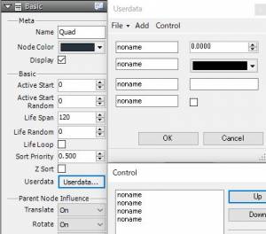
You can add to each type of node your own data as well as edit the data with the edit form.
You can apply names to data and programmers can use data obtained through Runtime APIs.
In fact, users that use their own data and programmers that conduct their own data processing can determine rules and input settings accordingly.
・File
| Import | Import and add user data for nodes from a specified file |
| Export | Export and save user data added to nodes to a specified file |
・Add
| Integer | Add integer data and its edit interface with spin control |
| Real Number | Add a small number of data points and their edit interface with spin control |
| Character String | Adit character data and its edit interface with edit box |
| Vector | Add X and Y and Z values and their edit interface with spin control |
| Color | Add R and G and B and A values and their edit interface with color picker |
| Truth Value | Add TRUE and FALSE values and their edit interface with the checkboxes |
・Control
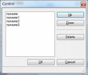 You can move selected user data up and down or delete it.
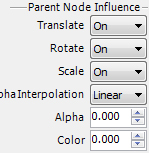
Parent Node Influence
Example for Utilizing User Data:
| Embed flag on whether you are going to use your own processing. |
| Embed the necessary parameters for your own processing(i.e. shader). |
| Move | Input settings on whether to influence when parent node moves or only when generated |
| Rotate | Input settings on whether to influence when parent node rotates not to influence or influence only when generated |
| Scale | Input settings on whether to influence when parent node is scaled not to influence or influence only when generated |
| Alpha Interpolation | Line Shape: Adds and displays alpha value for parent node Multiply: Multiplies and displays alpha value for parent node |
| Alpha | Input settings for alpha influence on parent node. Values are specified in a range from 0 to 1.
Alpha influence changes the the specifications. In old versions(versions prior to September 26 If you want to use the formulas for the new version |
| Color | Input settings to influence color of parent node. Values are specified in a range from 0 to 1. The formulas are as follows. color = your own color * (1.0f – color_rate) + (parent color)* color_rate When the color_rate is 0 the color is the original.When the color_rate is 1 the color is the parent color. |
※The default settings for Move, Rotate, and Scale are all set to “Influence”.
Reference Node Name
![]()
The parameter is displayed only when a reference object is selected. Import and use BMSLN files on these nodes.
For useable BMSLN files, go to the BMSLN folder inside the database folder.
BMSLN files including reference nodes cannot be used on reference nodes. The existing specifications apply.
It is not necessary to put BMSLN files that aren’t used on reference nodes into the BMSLN folder.
When executing a BMSLN file, the processing load is slightly higher when first initialized(due to calling up the file images from the file names) but the processing load is no different than when updating or drawing to create trees in the normal way.