Material
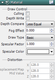
■Culling
Draw around the back side of a polygon.
■Depth Recording
Prevent rendering of duplicate polygons.
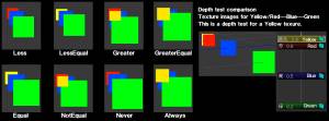
■Depth Test
Set Procedure for Depth Comparison
| Less | If the depth value of the pixels to be drawn is “smaller” then draw them. |
| Less Equal | This is the one normally selected. If the depth value of the pixels to be drawn is “smaller or the same as” the depth value then draw them. |
| Greater | Set if the clear depth value is negative. If the depth value of the pixels to be drawn “is larger” then draw them. |
| Greater Equal | Set if the clear depth value is negative. If the depth value of the pixels to be drawn is “greater than or the same” then draw them. |
| Equal | Display the pixels when their depth value is the same. Setting only for special expressions. |
| Not Equal | Display pixels when the pixel depth value is anything other than the same. Setting only for special expressions. |
| Never | Never display them. Setting only for special expressions. |
| Always | Consistently display effects at hand. Always draw pixels regardless of their depth value. |
■Fog Effect
When fog is applied, the degree of its effect is set between 0.0 and 1.0.
■Lighting
Set light to ON or OFF.(for Model nodes only)
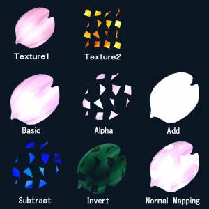
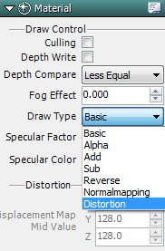
■Drawing Type
Specify the synthesis method for textures. ※See below for details.
■Specular Coefficient
Set the sharpness used for the specular. The drawing type can only be set for normal mapping.
■Specular Color
Set the specular color. The drawing type can only be set for normal mapping.
■Distortion
Set the central value for the distortion. Set R and G values between 0 and 255. The initial center value is 128.
①Change the “Drawing Type” for the Material to “Distortion”.
②Set texture to be distorted to Texture 1.
③Set distorted texture for Texture 2.
 |
In this image Texture 2 was cropped and animated. |
Here is a detailed explanation for displacement maps.
Distortion Displacement Maps
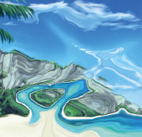
・Method for Distorting Backgrounds
Make the file name for Texture 1 “@backbuffer” and set Mapping Type to “Projection” to distort the background.
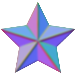
■Normal Mapping
・Normal mapping the 2nd image and the material by selecting “Normal Mapping” will result in a visually different image from typical normal mapping.
・You can indicate at the pixel level the normal direction as a texture and create uneven light reflections.
・Currently, normal map settings may be configured but we intend to make further functional improvements in future upgrades.Not a recommendedfunction.
・Models and stripes are not compatible with normal mapping(even though there is normal mapping in the material-image type tab).
Settings
①Select texture to apply normal mapping to Texture 1.
②Set Normal Mapping for Texture 2.
③Set material setting to “Normal Mapping”.
④Adjust “Specular Coefficient” and “Specular Color”.

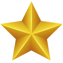
 This what it looks like.
※The following are the various drawing types.(from Version 1.8)
| Basic | Enable settings for only Texture 1 |
| Alpha | Synthesize transparency of Texture 1 and Texture 2 |
| Add | Synthesize by adding Texture 2 to Texture 1 |
| Subtract | Synthesize by subtracting Texture 2 from Texture 1 |
| Invert | Synthesize by inverting Texture 2 and combining with Texture 1 |
| Normal Mapping | Set Texture 1 to a normal texture and Texture 2 to normal map and apply light effects. ※Scrolling both Texture 2 with only normal mapping and Texture 1 at the same time is possible. |
| Distortion | style=”background-color: #e0e0e0;”Project the distortion level of Texture 2 onto Texture 1. |